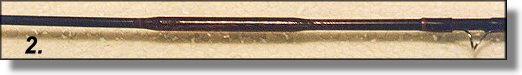
Number 2. The break shown last time was in an area that will not
see much flexure or bending. Under heavy load, the rod at this point will
be mostly straight, except when casting the line. The act of casting is
probably the peak load that this repair will ever see. As we go further up
the rod the bending becomes more severe. The break in No. 2 is about 14
inches from the tip. The bending moment is more pronounced in this area.
Your sleeve needs to be slightly longer in order to accommodate the longer
moment arm and slightly stiffer sections being joined. So increase the
length of this sleeve to about 1 & 1/2 inch to 1 & 3/4 inch over all, which will
mean that about 5/8 to 3/4 of an inch on each end will be structure. Don't
forget the tapered ends. The bend moment on this area will be quite severe.
Maybe enough for the graphite sections to rupture the low modulus sleeve
even though it is wrapped and coated. To counter this shearing force, we
will install a very small piece of either fiberglass or graphite on the
INSIDE. This piece must fit snugly, and be about 1/4 inch long. If it is
any longer it will be involved in the bending force and we don't want that.
Be sure that this piece is in place before you position the outer sleeve.
When the adhesive is cured, the sleeve is cleaned up and wrapped and
finished like any guide or ferrule. Grasp the rod about a foot on each side
of the repair sleeve and bend it into an arc with the repair in the center
of the arc. The arc should be constant - no noticeable flat spot at the
sleeve location. If there is a noticeable flat spot, then your sleeve is
either too long or too heavy, i.e., too thick a wall section.
TAPER TROUBLE
At this area on most any fly rod is where you will have to start allowing
for the taper of the blank when fitting a sleeve. The further back we go,
the worse the problem becomes. No problem fitting the rear section - the
largest OD - but depending upon the degree of taper - the front section can
be quite challenging . This particular area is still so far toward the tip
that the problem is very minimal. Your sleeve will fit very nicely over the
rear section, but to fit it on the forward section you will find that the ID
of the sleeve is smaller than the OD of the section that it must cover.
Some repairs on fast taper rods require the removal of all guides and the
tip in order to slide the sleeve into place. But what we have here is
merely a snug fit. The sleeve must be pushed a tad but that's all.
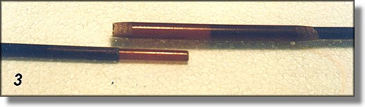
Number 3. Now that we are into real structure, this one has to be good in
every aspect or the rod is doomed. This is in the area of greatest flex
which means greatest bend load and fatigue factor. But mostly, it is an
area of sensitivity. You FEEL the rod in this general area and you want to
maintain that feel. You don't want a 6-weight fly rod to feel like a
4-weight or an 8-weight. It will feel like a 4-weight if we use the same
pattern of structure that we used in #2, because that design does not have
sufficient stiffness to work with the bend load of the graphite in this
area. To increase the stiffness using the same materiel, we merely have to
increase the 'I' moment, and this is easily accomplished by adding an
internal doubler. Calculating the amount of overlap for this internal
doubler or plug can be rather tricky. Too long and it will impede the flex
of the graphite and change the feel of the rod. Too short and it will not
support the external sleeve, making the rod feel wimpy and sluggish and it
will probably break after very little usage. I wish I knew of some simple
formula to apply here, but it dwindles down to a gut feeling combined with
experience plus a little logic thrown in for good measure. Any aerospace
stress engineer experienced in calculating design loads for wing structures
could whip out his Slide Rule, (whoops, that one dated me) er, I mean
calculator, and give you firm answers. But in the absence of calculable
direction, let's find out where logic leads us and if there are any
aerospace stress engineers out there - sound off. Take another piece of
graphite tip section of this same approximate weight and flex the same area
where we are making our repair. Flex it over a linear scale - 12 inch ruler
will do fine. As you flex the rod, note on the scale and ask yourself the
question, "If a piece were inside, how long (length) could it be before it
resisted the flexing?" I judged this one to be about 2 inches, but past
experience has taught me that about 1&1/2 inches is best in this location
for this weight of rod. Nevertheless I inadvertently went ahead and made
the internal plug 2 inches long. Another way to determine this length is to
figure that the overlap for the doubler will be between 3 and 4 times the
diameter. Remember now, this plug is made of fiberglass and it is a smaller
diameter than the rod, which means that by itself it will effect the
graphite about as much as a wet noodle. However, combined with the external
sleeve which we are about to construct, the graphite will have met its
match. See photo above. This plug is acting exactly like the plug 'ferrules'
on those rod blanks which design this type of ferrule such as Fisher, Scott,
etc. After all, a ferrule is merely a joint and that is what we are doing
here - making a joint. If it were going to be a ferrule, we would have to
beef up that area of the blank where the ferrule is inserted, both ends.
Then leave the end with the decreasing taper free to insert and disjoint at
will. But since this joint is not intended to be a ferrule, it must be
supported with an external sleeve similar to those we used in #1 and #2.
EXTERNAL SLEEVE
The external sleeve must ALWAYS overlap the internal plug. A general rule
of thumb for the overlap is twice the diameter at the overlap point. I like
to round things out to nice even numbers, so I used a 1/2 inch overlap in
this instance. Then add almost another 1/4 inch on each end for the taper
and you have a sleeve about 3 & 1/2 inches long. This overlap is critical to
the integrity of the joint, much more so when the plug is graphite, but even
as fiberglass it will exert stresses that could rupture the rod blank if the
load is not properly distributed. Remember now, there is maximum bend at
this point.
Your internal plug will be sized by inserting the selected piece of
fiberglass through the nearby ferrule and out the broken end. The broken
ends will have been smoothed and squared off prior to this point. Carefully
mark and cut the piece so that you wind up with a plug with 1 inch inside
the ferrule end and 1 inch extending, that will fit snugly inside the tip
end. As you do more and more of this type of repair on different sizes and
types of rods it will become apparent to you that the forward section should
have a little less plug length than the rear section and this ratio will
vary with the wall thickness, degree of taper, and location on the rod. In
our example here, the optimum is about 13/16 inch, but let's not quibble and
just make it 1 inch for now. With your plug cut and sized, be sure and
radius the ends. Round them off with a file at about a 45 degree angle.
This will prevent a sharp edge from gouging into the rod wall.
CONSTRUCTING THE SLEEVE
Select a piece of fiberglass rod section from what appears to be of the same
or similar taper, and preferably non-painted. The painted fiberglass rods
are the cheapies with thick walls and very coarse glass cloth construction.
These make very poor external sleeves. Match your selected piece with the
butt end of your joint - the larger end. Cut your fiberglass so that it
will fit over the end and extend past your internal plug about an inch,
which makes it about 2 inches total. Now trim your piece so that you have
an equal amount for the other end. You should have a piece for a potential
sleeve which is about 4 inches long at this point. Now you've got a
problem. How do you get that tapered sleeve over the tapered tip section
when the ID of the sleeve end is smaller than the OD of the rod end? You
can take off all the guides and slide it on from the tip. There are 6
guides and the tip top and this is almost always the quality way to do it.
So now it becomes a judgment call because there is a quicker (and easier)
method which does the job quite nicely. (Just don't let that stress
engineer from the wing group know what we're doing, cause he might get out
his slide rule and squash the whole deal.) First, size the sleeve to a net
fit on the butt end, which means that you will trim it to about 1&5/8 inch
overlap. Next, trim it to the same dimensions for the tip end. Touch the
end of the sleeve to the tip section end and see if the sleeve will slide
over and onto the tip section. It had better not! It easily slides over
the butt section, so put it there for now. The taper in the rod makes a
mismatch in diameters between the section of the tip end and the reinforcing
sleeve. The end of the sleeve will match the rod some 1&1/2 inches inboard
- which is where we want it to wind up. But how to get it there? Try this
- bevel the end of the sleeve that attaches to the tip section to about a 15
degree angle, or as shallow as you can handle. A power disk sander or belt
sander is ideal for this operation. Rotate the sleeve in your fingers as
you bevel and grind the end to zero. This beveled end will be quite flimsy,
so match it to the tip section again and this time force the tip section
into the beveled sleeve. Enter at a slight angle then push the rod section
further into the beveled area which will split the sleeve at this point.
This splitting will facilitate further movement until the sleeve is fully
installed on the tip section. The other end of the sleeve which attaches to
the butt section can now be beveled to the same degree. The splitting of
the sleeve has done nothing to impede its structural integrity. The split is
usually 1/4 to 1/2 of the length and is neutralized when the area is bonded,
wrapped and finish applied. This is considerably faster than removing and
replacing 6 guides and a tip top!
BONDING
The external surfaces of all pieces are prepared for bonding in the usual
manner, i.e., light abrasion of the surfaces with Scotchbrite or 400 grit
sandpaper. The inside of the rod pieces must be cleaned of loose particles
by swabbing them out with a small bottle brush, a doubled up pipe cleaner or
some similar instrument. Sometimes I use a small round file and on the
larger blanks - a small notched dowel with a piece of sandpaper inserted
into the notch and the other end chucked in my winding lathe jaws and
rotated inside the blank. You will need a piece of rod or a stick of some
kind to poke the internal plug all the way through the butt piece. Cover it
with the paste epoxy and insert it in the ferrule end and push it through
with your stick. Be sure and clean out the ferrule immediately. With the
plug snugly in place, add more epoxy to the exposed end and bond in place
the tip section The sleeve is loosely attached to this section, so slide
the sleeve toward the tip and away from the repair area - then liberally
coat the area toward the butt with epoxy, slide the sleeve over this epoxy
and rotate it several times in order to thoroughly coat the inside of the
sleeve. Now apply another thin coat of epoxy in the area of the repair and
slide the sleeve into its position. Wipe off the epoxy that is forward of
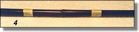
the sleeve, using IPA. With the sleeve in position, it must be wrapped.
The wrap will be a temporary one, as its only purpose is to hold all parts
snugly together while the epoxy cures. Since it must be wrapped very tight,
I normally use D thread. The split end will close and epoxy will be
squeezed out. When the epoxy has cured, there will be cleanup to do in the
area of the split and at each of the beveled ends. When the cleanup is
completed, apply your final wrap with a nice A thread to match the color
scheme of the rod and finish off with your favorite epoxy wrap finish.
~ R. O'Quinn
Next Time!
|